boxwarp
General linear tilting and sheering transformation.
Signatures
- boxwarp( vector g0, vector g1, vector g2, vector g3, vector h0, vector h1, vector h2, vector h3, vector h4, vector h5, vector h6, vector h7 )
Details
The boxwarp transformation provides a general way for applying tilting and sheering operations.
The basic idea is to map points from an initial coordinate system that is given by an initial box (or more general: a parallelepiped) g onto a second coordinate system of a second box (an 8-corner or hexahedron) h. Since the two boxes can be defined rather freely, this allows for a wide variety of different tilting and sheering forms.
Note that the solids the transformation is applied to are not required to be covered by either box g or box h. The boxes only define the transformation which extends onto all space points inside and outside of the boxes themselves.
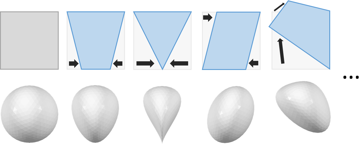
The input (left) and four possible boxwarp transformations (right). The upper row shows the input box g in grey and the transformation boxes h in blue while the lower line displays the respective deformations of a sphere.
The inital box g is given as a general parallelepiped that is defined by four of its corner points g0, g1, g2 and g3. The required positions of these point with respect to each other can be seen in the following figure:
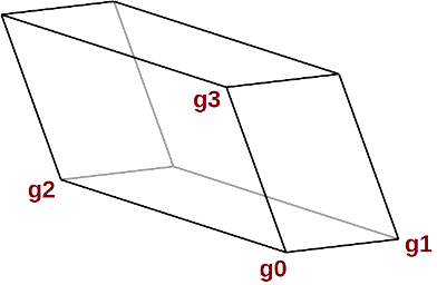
The initial parallelepiped g defined by its four corner points g0 to g3.
The second box h is a general 8-corner or hexahedron with its eight corners set like in the following image:
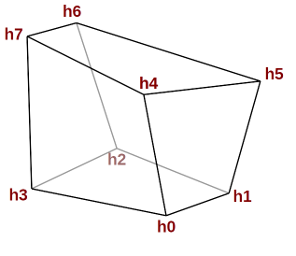
The target box h defined by its eight corner points h0 to h7.
Example
 make boxwarp( <[0.0, 0.0, 0.0]>, <[1.0, 0.0, 0.0]>,  <[0.0, 1.0, 0.0]>,  <[0.0, 0.0, 1.0]>,
               <[0.0, 0.0, 0.0]>, <[2.0, 0.0, 0.0]>,  <[2.0, 2.0, 0.0]>,  <[0.0, 2.0, 0.0]>,
               <[-0.5, -0.5, 1.0]>, <[2.5, -0.5, 1.0]>,  <[2.5, 2.5, 1.0]>,  <[-0.5, 2.5, 1.0]> ) >>
      cylinder( 2.0, 1.0, 0.5  )
Casts To
Parameters
- g0
-
The first corner point of the initial parallelepiped g.
- g1
-
A second corner point of the initial parallelepiped g that is a neighbor to g0 along the first edge axis.
- g2
-
A third corner point of the initial parallelepiped g that is a neighbor to g0 along the second edge axis.
- g1
-
A fourth corner point of the initial parallelepiped g that is a neighbor to g0 along the third edge axis.
- h0
-
The first corner point of the target hexahedron h.
- h1
-
The second corner point of the target hexahedron h.
- h2
-
The third corner point of the target hexahedron h.
- h3
-
The fourth corner point of the target hexahedron h.
- h4
-
The fifth corner point of the target hexahedron h.
- h5
-
The sixth corner point of the target hexahedron h.
- h6
-
The seventh corner point of the target hexahedron h.
- h7
-
The eigth corner point of the target hexahedron h.