Bangle tutorial
As an example let’s make a simple customizable bangle.
A configurator using the trcad script explained in this tutorial could look like this. The control values on the right side can be adjusted to customize the bangle.
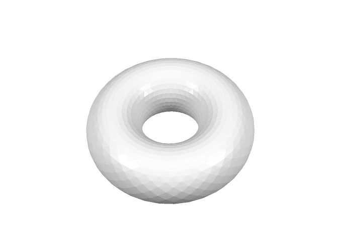
Let’s start with a simple ring.
In trCAD a ring can be generated by using the build-in function torus. In the most basic form this is done by the code:
torus()
This will return a solid of a torus with 0.5 mm tube radius and 1 mm torus radius. This solid can be used for further construction. To get this solid in the mesh output it needs to be made. This is simply done by the command make:
make torus()
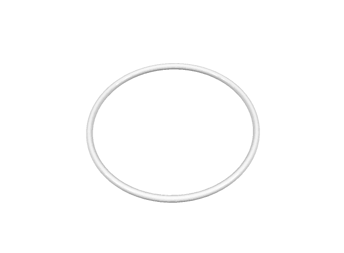
For a bangle we want to define the thickness and the radius of the ring. For this we can use the torus-function with signature
solid torus(float torusRad, float torusTubeRad)
Let’s say the Ring should have a thickness of 3.0 mm and an inner diameter of 70 mm. To get this, the tube radius should be half of the thickness and the torus radius, being the radius of the tube center line, is to be the inner radius plus the tube radius. Let’s put this in code:
float ringThickness = 3.0
float innerDiam = 70
float torusTubeRad = 0.5 * ringThickness
float torusRad = 0.5 * innerDiam + torusTubeRad
make torus(torusRad, torusTubeRad)
Now if you want to have your bangle with a different diameter, you could just change the variable innerDiam to something else directly in the code, but how can we make a customizer out of that, that can be operated without having to edit the code? In trCAD this is very easy. All you have to do is take the variable that you want to be changeable from the outside and make an open parameter out of it. For a float parameter this is done for example with this code block for the variable innerDiam:
open float innerDiam
{
name = "Diameter"
descr = "Inner Diameter of Bangle"
value = 70.0
}
Besides the default value value you have to provide information for how to label and describe the open parameter. This is done by the string variables name and descr. These can be shown to the user so that he knows what this open parameter is. In the trCAD-editor and when using paramate to generate web-customizers, for each open parameter a control element can be generated automatically, by default being a simple edit field for a float open parameter.
When putting this code block in your code instead of the line float innerDiam = 70 the full code will be
float ringThickness = 3.0
open float innerDiam
{
name = "Diameter"
descr = "Inner Diameter of Bangle"
value = 70.0
}
float torusTubeRad = 0.5 * ringThickness
float torusRad = 0.5 * innerDiam + torusTubeRad
make torus(torusRad, torusTubeRad)
Now the diameter can be set from outside the code and you have done your first, simple customizer script!
Now let’s make the bangle customizer a bit more interesting with more functionality and more open parameters. How about some color? Color can be added to a solid by defining a color variable and then applying it as a modifier. In trCAD colors can be defined in two variants, RGB or CMYK. For our example RGB-color will be fine. The signature is simply
color rgb(int r, int g, int b)
so rgb(255,0,0) gives red.
Applying this as a modifier to a solid is easy. This code will return a torus in red:
rgb(255,0,0) >> torus()
And it can be made in just one line:
make rgb(255,0,0) >> torus()
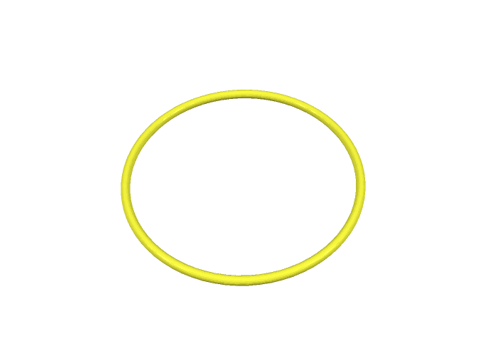
A color variable can be made an open parameter in a similar way like a float variable by the code block
open color myColor
{
name = "Color"
descr = "Color of Bangle"
value = rgb(255,255,0)
}
By default this generates a color-picker control element in the trCAD-editor or when using the paramate automatic controls for a web-customizer, where the default value rgb(255,255,0) (yellow) is pre-selected.
Let’s put this in your bangle customizer, the full code will be
float ringThickness = 3.0
open float innerDiam
{
name = "Diameter"
descr = "Inner Diameter of Bangle"
value = 70.0
}
float torusTubeRad = 0.5 * ringThickness
float torusRad = 0.5 * innerDiam + torusTubeRad
open color myColor
{
name = "Color"
descr = "Color of Bangle"
value = rgb(255,255,0)
}
make myColor >> torus(torusRad, torusTubeRad)
Now a user can choose the diameter and the color of the bangle.
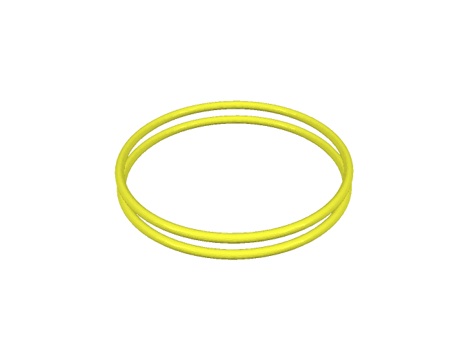
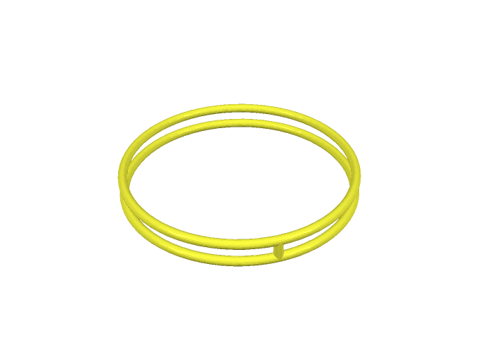
Let’s make the bangle a bit more interesting, for the start having two rings instead of one, and let’s say we want to have one ring thickness distance between the two rings. The easiest way to get this would be to just make another ring translated the desired distance from the first ring, using the build-in translation modifier. The code to be added would be
float ringsDist = 2 * ringThickness
make myColor >> translation(<[0,0, ringsDist]>) >> torus(torusRad, torusTubeRad)
By default a torus is generated with the symmetry axis being the z-axis, so here when we want to have the second ring ringsDist above the first one, we have to translate this distance in z-direction, so the translation argument is the vector <[0,0, ringsDist]> (for more on vectors see the manual).
Although we could write the code in the way given above, it is not very convenient or clean to read it like that, because we have to apply the color to each of the rings separately and call the torus function twice. If we want to have more rings it will get even messier. So now it is a good time to clean up our code a bit so that we can more easily add more features to our bangle.
It is a good practice to define one solid, in which we can step by step add up our final solid, then just apply color once and make the resulting solid in one go. Solids are just a normal type of variable in trCAD and solids can be combined by boolean operations. There are three types of boolean operations supported (union, difference, and intersection), but for our example case we just need the union, adding two solids to one (removing the parts of the solids where they intersect).
A solid named myObject is declared by
solid myObject
One solid myObject can have a second solid mySecondObject added to it via boolean union simply by using the + operator
myObject = myObject + mySecondObject
which can be written in short as
myObject += mySecondObject
In a similar way a modifier myModifier can be applied
myObject = myModifier >> myObject
which can be written in short as
myObject <<= myModifier
(notice that the arrows always point to the solid they are applied to).
Knowing this you can change your code for the two rings, using one solid variable for building up your object and one for elegantly storing the base ring for multiple use:
solid myObject
float ringThickness = 3.0
open float innerDiam
{
name = "Diameter"
descr = "Inner Diameter of Bangle"
value = 70.0
}
float torusTubeRad = 0.5 * ringThickness
float torusRad = 0.5 * innerDiam + torusTubeRad
solid baseRing = torus(torusRad, torusTubeRad)
float ringsDist = 2 * ringThickness
myObject = baseRing
myObject += translation(<[0,0, ringsDist]>) >> baseRing
open color myColor
{
name = "Color"
descr = "Color of Bangle"
value = rgb(255,255,0)
}
myObject <<= myColor
make myObject
When we have two rings, why not make the number of rings an open parameter? Generate an open parameter for the number of rings using an open int variable:
open int nRings
{
name = "Rings"
descr = "Number of Rings"
value = 2
}
Now, to generate the desired number of rings, where the number is only defined upon run-time, using a for-loop comes in handy. To gain a distance of ringsDist between each ring the distance each one has to be translated from the position of the base ring is i * ringsDist, i = 0,...,nRings-1. Let’s build the for-loop out of that:
for(int i = 0; i < nRings; i++)
{
myObject += translation(<[0,0, i * ringsDist]>) >> baseRing
}
The full script now looks like this:
solid myObject
float ringThickness = 3.0
open float innerDiam
{
name = "Diameter"
descr = "Inner Diameter of Bangle"
value = 70.0
}
float torusTubeRad = 0.5 * ringThickness
float torusRad = 0.5 * innerDiam + torusTubeRad
solid baseRing = torus(torusRad, torusTubeRad)
open int nRings
{
name = "Rings"
descr = "Number of Rings"
value = 2
}
float ringsDist = 2 * ringThickness
for(int i = 0; i < nRings; i++)
{
myObject += translation(<[0,0, i * ringsDist]>) >> baseRing
}
open color myColor
{
name = "Color"
descr = "Color of Bangle"
value = rgb(255,255,0)
}
myObject <<= myColor
make myObject
So now the customizer lets the user choose what color, how many rings, and which diameter the bangle should have. But since we just stacked rings with a distance in-between the rings will not hold together or stay at the set distance when 3D-printed. So we need to make the design better and add connectors to hold the rings in the desired position. Let’s take a cylinder as connector, having the same thickness as the rings, starting from the middle level of the lower-most ring and ending at the middle level of the upper-most ring. So the length of the cylinder needs to be exactly (nRings - 1) * ringsDist and depends on how many rings we have and the radius of the cylinder is just the same as the radius of the torus tube torusTubeRad.
In trCAD a cylinder can be generated by using the build-in function cylinder. For defining the radius and the length of the cylinder, use the cylinder-function with signature
solid cylinder(connectorLen, connectorRad)
This will generate a solid of a cylinder with length going in z-direction, positioned at the origin in x-y-direction, so right in the center of the ring. To connect the rings the cylinder needs to be positioned with its x-y-center on the torus central line, so for example at x = torusRad, y = 0. So the connector needs to be translated this amount in x-direction. Let’s add the connector to the code:
solid myObject
float ringThickness = 3.0
open float innerDiam
{
name = "Diameter"
descr = "Inner Diameter of Bangle"
value = 70.0
}
float torusTubeRad = 0.5 * ringThickness
float torusRad = 0.5 * innerDiam + torusTubeRad
solid baseRing = torus(torusRad, torusTubeRad)
open int nRings
{
name = "Rings"
descr = "Number of Rings"
value = 2
}
float ringsDist = 2 * ringThickness
for(int i = 0; i < nRings; i++)
{
myObject += translation(<[0,0, i * ringsDist]>) >> baseRing
}
float connectorLen = (nRings - 1) * ringsDist
float connectorRad = torusTubeRad
solid connector = cylinder(connectorLen, connectorRad)
connector <<= translation(<[torusRad,0,0]>)
myObject += connector
open color myColor
{
name = "Color"
descr = "Color of Bangle"
value = rgb(255,255,0)
}
myObject <<= myColor
make myObject
(Note that for nRings = 1 we do not need any connector and the connector has length 0 in the code. trCAD detects that and does not make the cylinder at all, so this is not a problem. It would be cleaner to make an if-clause only running this part of the code for nRings > 1, but for keeping it simple, we leave that out.)
Now one connector holds the rings. But why not have more connectors and let the user choose how many? So let’s put an open parameter for this
open int nConnectors
{
name = "Connectors"
descr = "Number of Connectors"
value = 1
}
For distributing the connectors evenly, take the total angle on the circle (2 Pi) and distribute it evenly on the connectors, so an angle of 2 Pi divided by the number of connectors for each. 2PI is a pre-defined constant in trCAD and can be used for the calculation of the angle per connector:
float anglePerConnector = 2PI/nConnectors
Starting from the position of the first connector, each connector needs to be rotated around the z-axis with angle i * anglePerConnector, i = 0,..., nConnectors-1, using the rotation modifier, with the first argument being the rotation axis and the second argument the rotation angle. So the for-loop for adding the connectors looks like this:
for(int i = 0; i < nConnectors; i++)
{
myObject += rotation(<[0,0,1]>, i * anglePerConnector) >> connector
}
Add all of that to the code:
solid myObject
float ringThickness = 3.0
open float innerDiam
{
name = "Diameter"
descr = "Inner Diameter of Bangle"
value = 70.0
}
float torusTubeRad = 0.5 * ringThickness
float torusRad = 0.5 * innerDiam + torusTubeRad
solid baseRing = torus(torusRad, torusTubeRad)
open int nRings
{
name = "Rings"
descr = "Number of Rings"
value = 2
}
float ringsDist = 2 * ringThickness
for(int i = 0; i < nRings; i++)
{
myObject += translation(<[0,0, i * ringsDist]>) >> baseRing
}
float connectorLen = (nRings - 1) * ringsDist
float connectorRad = torusTubeRad
solid connector = cylinder(connectorLen, connectorRad)
connector <<= translation(<[torusRad,0,0]>)
open int nConnectors
{
name = "Connectors"
descr = "Number of Connectors"
value = 1
}
float anglePerConnector = 2PI/nConnectors
for(int i = 0; i < nConnectors; i++)
{
myObject += rotation(<[0,0,1]>, i * anglePerConnector) >> connector
}
open color myColor
{
name = "Color"
descr = "Color of Bangle"
value = rgb(255,255,0)
}
myObject <<= myColor
make myObject
Now a user can choose how many connectors he wants. But this allows for choosing zero connectors as well. The same problem is there for the diameter and the number of rings, the user can choose any number and size. That is not good. The customizer should always generate a reasonable bangle and keep the user safe from choosing stupid values. For this trCAD supports setting allowance boundaries for numerical open parameters, in the simplest way setting static minimum and maximum values. Like the value attribute, for the numerical open parameters a min and a max value can be set.
Let’s use this and set boundries for the open parameters. For innerDiam min = 40.0, max = 90.0, for nRings min = 1, max = 8, for nConnectors min = 1, max = 10. The final code looks like that:
solid myObject
float ringThickness = 3.0
open float innerDiam
{
name = "Diameter"
descr = "Inner Diameter of Bangle"
value = 70.0
min = 40.0
max = 90.0
}
float torusTubeRad = 0.5 * ringThickness
float torusRad = 0.5 * innerDiam + torusTubeRad
solid baseRing = torus(torusRad, torusTubeRad)
open int nRings
{
name = "Rings"
descr = "Number of Rings"
value = 2
min = 1
max = 8
}
float ringsDist = 2 * ringThickness
for(int i = 0; i < nRings; i++)
{
myObject += translation(<[0,0, i * ringsDist]>) >> baseRing
}
float connectorLen = (nRings - 1) * ringsDist
float connectorRad = torusTubeRad
solid connector = cylinder(connectorLen, connectorRad)
connector <<= translation(<[torusRad,0,0]>)
open int nConnectors
{
name = "Connectors"
descr = "Number of Connectors"
value = 1
min = 1
max = 10
}
float anglePerConnector = 2PI/nConnectors
for(int i = 0; i < nConnectors; i++)
{
myObject += rotation(<[0,0,1]>, i * anglePerConnector) >> connector
}
open color myColor
{
name = "Color"
descr = "Color of Bangle"
value = rgb(255,255,0)
}
myObject <<= myColor
make myObject
This is the end of this example. We showed some basic concepts of construction solids using simple geometrical forms, setting up open parameters for users to choose from outside the code and setting reasonable boundaries for these parameters, showed how to use some simple modifiers to change position and color and some basic usage of loops.
There is much more functionality in trCAD, have a look at the manual to learn more.
Learn how to set up a web-customizer using your trCAD script with paramate in the paramate-walkthrough.