extrusion
Creates a solid by extrusion of a curve or sketch.
Signatures
- extrusion( sketch outline, vector span )
- extrusion( sketch outline, curve path )
- extrusion( sketch outline, curve path, vector normBegin, vector normEnd )
- extrusion( sketch outline, vector origin2d, curve path )
- extrusion( sketch outline, vector origin2d, curve path, vector normBegin, vector normEnd )
- extrusion( sketch outline, vector origin2d, vector dir2d, curve path )
- extrusion( sketch outline, vector origin2d, vector dir2d, curve path, vector normBegin, vector normEnd )
- extrusion( sketch outline, vector origin2d, vector dir2d, curve path, vector dir3d )
- extrusion( sketch outline, vector origin2d, vector dir2d, curve path, vector dir3d, vector normBegin, vector normEnd )
Details
The function creates a solid object from a 2d sketch (i.e. a sketch in the x/y plane) by applying an extrusion operation.
When extruding along a path, the sketch is carried along the curve as a cross-section frame. Its placement at every point of the path is fully determined by three things: the
In practical terms: origin2d chooses where the profile seats on the path, dir2d and dir3d choose how it is rotated about the path, and the profile's out-of-plane axis automatically becomes the tangential direction.
For constructors (1), (2), (4), (6) and (8), the terminal planes are automatically aligned orthogonally to the direction of the path at its two ends. Constructors (3), (5), (7) and (9) allow to align the terminal planes at the beginning and at the end of the path manually.
Example
 curve star
 for( int i = 0; i < 36; ++i )
 {
   float rad = ( i % 2 ) ? 2.0 : 3.0
   star ->= rad * <[ cos( rad( i * 10 ) ), sin( rad( i * 10 ) ) ]>
 }
 star = star -><-
 make extrusion( star, <[0.0, 0.0, 1.0]> )

A simple star created as an extruded curve.
Example
 vector origin2d( 16, 12 )
 vector dir2d( 1, 0 )
 vector dir3d( 1, -1, 0)

 sketch letterR =
   ( <[0,0]> -> <[8,0]> -> <[8,12]> -> <[16,0]> -> <[24,0]> -> origin2d ->
     arc_to( <[16,32]>, 10 ) -> <[0,32]> -><- ) -
   ( <[8,18]> -> <[14,18]> -> arc_to( <[14,26]>, 4 ) -> <[8,26]> -><- )

 curve path = <[50,0,0]> -> <[50,0,8]> ->
   bezier( <[50,0,18]>, <[54,4,18]>, <[54,4,28]> ) -> <[54,4,36]>

 color red = rgb(255,0,0)
 color green = rgb(0,255,0)
 make red >> extrusion( letterR, <[0,0,36]> )
 make green >> extrusion( letterR, origin2d, dir2d, path, dir3d )
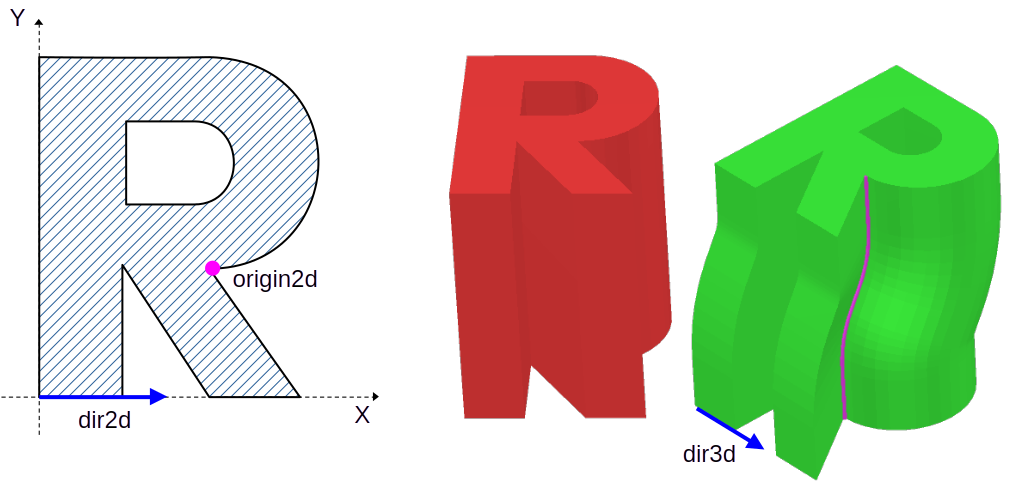
The left side shows the profile of the letter 'R' as constructed on the X/Y plane. The position that serves as origin2d and the dir2d direction are marked. The right side shows the same profile once extruded along a span vector (red) and along a given path (green). Note that point origin2d rides on the path (purple line) and the profile cross section is oriented so that its dir2d vector aligns with dir3d.
Note
The current version does not check for
Return value
A solid that is created by extrusion of the outline sketch.
Parameters
- outline
-
The 2-dimensional sketch that gets extruded. If this is not closed, it will be closed before extrusion.
- span
-
A vector that defines the extrusion.
- path
-
A curve that defines the extrusion.
- normBegin
-
A vector that determines the plane normal of the sketch at the beginning of the path extrusion.
- normEnd
-
A vector that determines the plane normal of the sketch at the end of the path extrusion.
- origin2d
-
The
anchor point of the cross-section: the point on the sketch that is placed directly onto the extrusion path. Every other point of the sketch is positioned relative to it, so choosing a different origin2d shifts the profile relative to the path. Default value is the origin of the coordinate system (0,0). - dir2d
-
A direction in the sketch plane that is used for orienting the extrusion about the path. At the beginning of the path the sketch is rotated so that dir2d aligns with dir3d (when given), or with the curve orientation at that point when dir3d is omitted. Choosing a different dir2d rotates the profile about the path.
- dir3d
-
An orientation direction in 3d space that dir2d is aligned to at the beginning of the extrusion path. It determines how the cross-section is rotated about the path relative to the world. If this parameter is not present, the orientation of the curve at this point is used instead.
