Enfolding and Infolding
For some applications it is useful to adapt a predefined solid to another one by "pressing" it onto the second solid's surface. In the medical area, for example, this could be an orthosis that is adapted to the scan of a limb of a patient to get a high-quality fit. Such an operation can be achieved with the help of the enfold function and its inverse counterpart, the infold function.
The basic concept of the enfold function is this: wrap or press one object A onto the surface of another object B (or a group of objects B) while preserving the thickness and small details of A. This has some similarities to pressing a clay model onto a rigid one or to a physical vacuum forming process.
Movement Modes
Several options exist for controlling the movement of A on the enfold operation. The first one is to define a fixed direction by providing a vector as function argument. All parts of solid A are then translated into this direction until they get blocked by object B. Note that a movement into the opposite direction is applied by the infold function.
A second option is to use a cynosure object (or object group). This is a set of space points or curves that act as center of attraction for A in case of the enfold function and as center of repulsion in case of the infold operation.
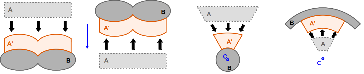
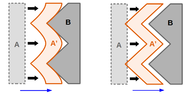
The figure display the different movement modes for enfolding or infolding of an object A onto another object B. The leftmost image shows an enfold operation with a movement into a fixed direction, the second image from left an infold operation using the same direction vector. The third image from left depicts an enfold operation with attractive cynosure C while the rightmost image is an infold movement with repulsive C.
The cynosure object or object group is handed over to the enfold/infold function in form of a curve object. This can either be a point or a general curve in space:
Example
curve c1 = <[0,6,2]>
curve c2 = <[-1,2,0]> -> line_to( <[0,3,-2]> )
If a set of cynosure curve is used, the curves are handed over as an array to the enfold or infold functions:
Example
make enfold( a, b, [c1, c2] )
Solid A
Solid A is the object that is moved and deformed in order to create the result of the enfold or infold operations. There are no specific requirements for A other than that its size and position must be adequate to allow the requested movement. The operation only modifies the positions of vertices of the fundamental mesh of A and is thus isomorphic.
Note that the enfold and infold operations are designed to exhibit a certain robustness agains the positioning of solid A with respect to solid B in the sense that A may intersect with B slightly.
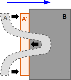
The picture depicts the behavior of the enfold function if A contains small intersections with B: the respective areas of A are getting "driven out" of B.
Filtering
In addition to the bare operations, some tuning parameters can be set to the enfold and infold function. The first one activates the filter feature that effectively implements a low-pass filter that simulates a certain "stiffness" of the material of A. The governing parameter is the filter length. In terms of stiffness, this parameter corresponds to the effective bending radius of the surface of A. Note that this correspondence matches best if edges of the triangle mesh representing A have more or less equal lengths.
The effect of filtering. The image on the left side shows the application of an enfold operation without filtering, the right side an activated low-pass filter.
The filter feature can be useful in different scenarios: since the enfold and infold operations relocate every vertex of A along a line (that is either given by the direction vector or the cynosure) until it is blocked by B (under considation of the material width) some effects can occur that might not be expected in the first place. So are small features of B reproduced onto the shape of A. Another effect might be that borders of A collaps onto B what results in a kind of tilting or folding. Both effects are shown schematically in the following figure.
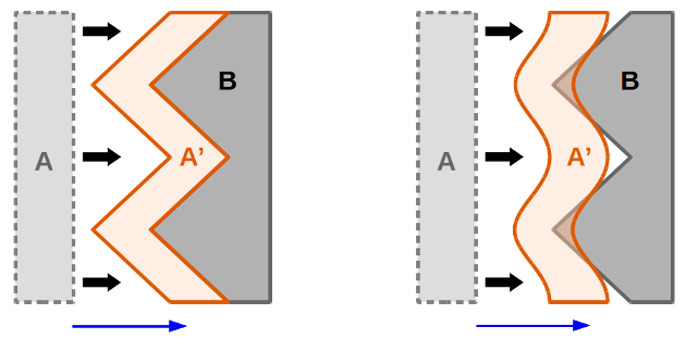
Two different types of unexpected effects that may occur during enfolding/infolding. The left image shows the reproduction of a small feature of B on A', the right image a collapse of the upper left corner of A onto B.
The filter function can countervail these effects to some degree.
Note
Large filter length values may lead to longer execution times.
"Strict" Mode and Offset
One side effect of applying a low-pass filter might be that the result intersects with B due to the stiffness applied. This can be countered by activating strict mode. This ensures that all vertices of the mesh of A are effectively driven out of B (see figure).
In addition, an offset can be applied that shifts all vertices of the mesh of A by the respective factor. This offset value may be positive (moving vertices of A away from B) or negative (moving them into B).
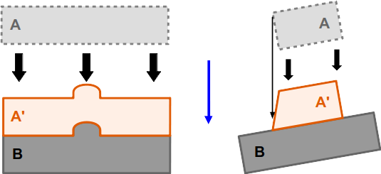
The left image shows the effect of the "strict mode" that pushes peaks out of B even on applying an effective filter. The image on the right shows the effect of a (positive) offset.
Tips and Tricks
Despite its apparently simple nature, the enfold and infold functions obtain sufficient subtleties that might make it hard to reach a desired shape on the first try. However there are a number of practices that may help to handle the operations better and obtain optimal results.
Subdivision of A
The enfold and infold functions are isomorphic operations acting on the mesh representation of solid A by moving its vertices only. No additional triangles or vertices are added. Starting with a mesh A of low resolution might end up in poor results. This accounts for other morphing operations like bending or helix as well. The solution is in such a case to increase the mesh resolution of A sufficiently high, e.g. by applying the subdiv modifier.
Centering Cynosure
In a configuration where A is meant to wrap around an inner object B, the cynosure should be well centered inside B. Otherwise some streching effects might occur on the result (see figure). If B exhibits a less trivial shape, it may be useful to add more than one cynosure and form a central structure that guides all surface areas of A harmonically towards the surface of B.
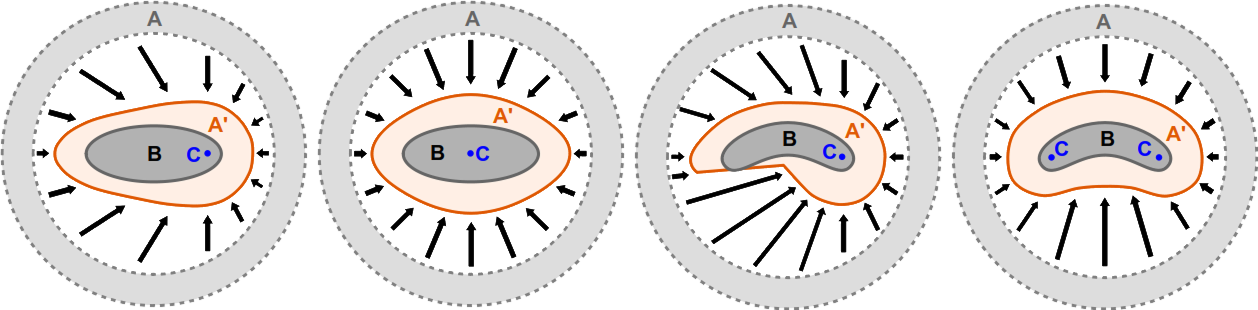
The advantageous effect of centering the cynosure of an enfold operation is shown in the two left images: since the cynosure C on the leftmost picture is not well-centered on B, the shape of the result is quite asymmetrical. This was corrected on the second image. The third picture from left shows an unwanted steep feature that arises from a single off-center cynosure inside a solid B of more complex shape. By using of two cynosures, a better effective centering could be achieved.
Approaching Surface of B
The option to use multiple cynosures in an enfold or infold operation suggests to pay some attention to the movement of a single surface points of A under such circumstances. The following sketch depicts the movement of different points of A in the proximity of two cynosure elements. As one can see, point A3 does not propagate towards any of the cynosures since it is situated on the central line of C1 and C2. This configuration can be compared to a slingshot setup. This effect can lead to unwanted behavior, if A is located at such a position.
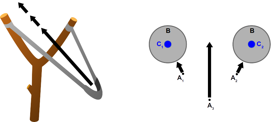
The right image displays the movement of three potential surface points of A. Point A3 resides on the central axis between the two cynosure elements. Its trajectory can be compared to that of a slingshot (left image). This movement will not be blocked by solid B in the example.
In many cases, such a "slingshot" situation can be avoided by starting with a solid A that has a geometry that is already close to the surface of B. This can be done without concern of creating intersections with B since these are handled well by the enfold or infold function.
Adding a Protection Sheet
As stated earlier, one problem that may occur is the collaps of steep edges of A towards B due to a slightly tilted movement direction. This may result in notched borders of the resulting solid as shown in the example below for a hole pattern structure.
There are several options when this problem occurs. One option is to apply a low-pass filter. Another solution might be to reshape the model A in way that the respective edges exhibit tilted slopes instead of straight ones.
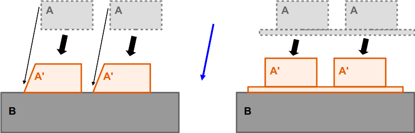
The left image shows the effect of collapsing edges caused by a tilted movement direction: the upper left corners of the two blocks of A are moved onto B leading to a "notched border" situation. Note that the effect may also occur at much smaller tilt angles. The image on the right displays how a protection layer preserves the original shape of A.
Another way of fixing the problem is by adding a thin protection sheet between A and B. This is added to object A and defines where its "base line" is. This procedure can avoid the edge collaps completely. The layer can be quite thin (e.g. 0.0001 length units) and the position shift of the result may be compensated by a negative offset of this thickness. The sheet is later removed using the split() method on the resulting solid.
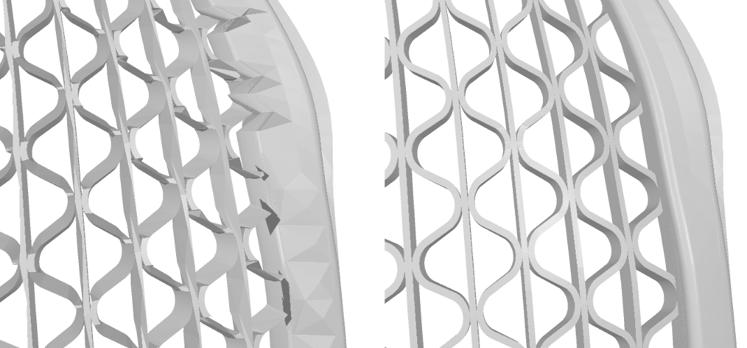
Effects of the usage of a protection sheet. The left images shows the result of an enfold operation that exhibits severe damage due to egde collapsing. The right image shows the result of the same operation using a protection sheet (not visible).
Apply Smoothing
Sometimes none of the approaches presented before leads to an optimal result. In such cases there is the option to use a smoothing operation (i.e. smoothing(0.0, 50)) and see whether is improves the shape any further.