Biselection Modification
For certain constructions it may be useful to apply two modifiers on different parts of one object. This could be that one part of the object is moved or changed while the other part shall stay fixed or that both parts are moved or changed differently with respect to each other. In these cases, the biselection modification function of trCAD comes handy.
The tool is a build-in function with the signature
biselect_mod( solid, selection, modifier, selection, modifier )
The operation of the function can be understood from looking at its arguments:
- 1: the solid that is modified by the operation.
- 2: a selection s1 that selects a partial region of the solid.
- 3: a modifier m1 that will be applied to the region of the solid selected by s1.
- 4: another selection s2 on the solid.
- 5: a modifier m2 that will be applied to the region selected by s2.
There are two main ways to use the biselect_mod function:
1. Disjoint Selections with Elastic Region
It is expected that regions s1 and s2 are disjoint. It is important to note that there may be some region that is neither covered by s1 nor s2. This intermediate zone of the solid between the two selections will be the elastic region when the function is applied.
When the function is called, it applies the two modifiers to the two parts of the solid that are selected by the two selections. The part of the solid that forms the intermediate zone is deformed elastically in a way that it smoothly fits to the boundaries of the selections. This is done by adjusting the vertex points of the triangulation mesh that forms the object. This means that if the mesh is too coarse, the elastic effect becomes unpronounced. The intermediate zone can be empty, small, big or even extended over the whole solid, depending on the requirements of the construction.
The function then returns the resulting solid.
The following example shows, how the biselect_mod function can be used to animate a figur coming from a 3D scan. It defines a rotation transformation via a rotation center, a rotation axis and an angle and applies it to the hand of the figure while the body is kept fixed. The arm is deformed elastically to fulfill the boundary conditions on both selections. Please note that the elbow's position is fixed by positioning the rotation center in the middle of the elbow.
Example
solid object = mesh( "myfiles/figure.stl" )
selection s1 = selectbox( -11.0, 1.9, -3.0, 10.0, -5.0, 20.0 )
selection s2 = selectsphere( 1.0, <[ 6.5, 1.7, 8.5 ]> )
vector center = <[ 3.4, 2.3, 9.8 ]>
vector axis = <[ 0.05, -0.98, 0.20 ]>
make biselect_mod( object, s1, identity(), s2, rotation( center, axis, rad( 64.0 ) ) )
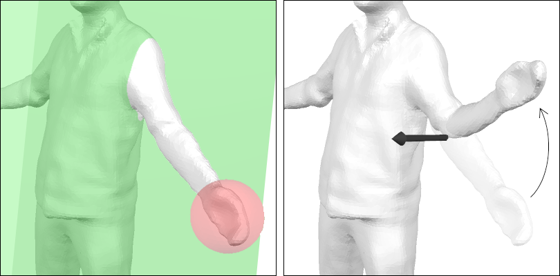
The image on the left shows the original object with the two selection s1 (green) and s2 (red). On the right, the transition to the resulting object is shown together with the rotation axis (big black arrow) of the applied transformation. See how the unselected parts of the figure's arm are adjusted elastically to follow the transformation.
Note
The quality of the results of the transformation of the elastic section depends strongly on the solid's resolution in that place. Poor resultions will lead to badly rounded, "edgy" results. This can be optimized with the subdiv modifier.
2. One Selection Covers the Whole Solid (No Elastic Region)
Alternatively, the function can be used in a mode where the second selection s2 covers the entire solid, and the corresponding modifier is typically identity. In this case, the first selection s1 selects a part of the object to be modified independently from the rest. The rest of the object (outside s1) remains unchanged. In this mode, there is no elastic region between the selections, and the transition between the modified and unmodified regions may be sharp, possibly resulting in visible kinks or discontinuities, depending on the nature of the applied modifier.
This approach is useful for creating objects with abrupt transitions, such as a "sugar cane" geometry, where only the top part of a cylinder is bent.
Example
// A simple cylinder (subdivided)
float radius = 0.5
float height = 10.0
solid cyl = subdiv( 0.25, <[0.0, 0.0, 1.0]> ) >> cylinder( height, radius )

// Selecion of upper half of the cylinder
selectbox top( -radius, radius, -radius, radius, height * 0.5, height )

// Use biselect_mod() to bend the upper half of the cylinder
make biselect_mod( cyl,
                   top,
                   bending( 2.0, <[1.0, 0.0]>, <[0.0, 0.0, height * 0.5]>, <[0.0, 0.0, 1.0]> ),
                   cyl.min_bbox(),
                   identity() )
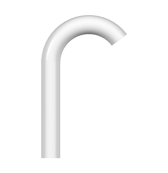
A cylinder bend in parts using the biselect_mod() function. Note that there is no elastic area between the two parts modified.
Note
In this mode, the transition between the modified and unmodified regions is not smoothed, and kinks may appear at the selection boundary.